Chinese
 English
 français
 Deutsch
 italiano
 español
 português
 Nederlands
 日本語




Tabless Cylindrical Battery Manufacturing Guide
Tabless cylindrical batteries are moving from a large-format innovation into a broader manufacturing platform for 18650, 21700 and other cylindrical cell formats. By replacing one or several discrete tabs with a continuous current-collection edge, the architecture shortens the electron path, distributes current more evenly and reduces localized heating. These advantages support high-power applications such as cordless tools, robots, drones, electric mobility and data-center backup systems. However, the electrical concept is only valuable when winding, current-collector forming, laser welding, electrolyte wetting and quality control can be executed as one stable process chain.

What Is a Tabless Cylindrical Battery?
A conventional cylindrical cell uses one or a few welded tabs to connect the coated electrode foils to the terminal structure. During charge and discharge, current must travel laterally through the current collector before reaching those limited connection points. The longer the electrode and the higher the current, the more important the resulting ohmic loss and local temperature gradients become.
A tabless design changes the current path. Instead of relying on isolated tabs, the uncoated edge of the current collector is segmented or shaped around the full circumference of the jelly roll. After winding, this edge is formed into an electrically conductive end face and joined to a collector plate or terminal. “Tabless” therefore does not mean that no current-collection interface exists. It means that a distributed, near-continuous interface replaces a small number of discrete tabs.
The distinction matters when comparing products. Some manufacturers use the terms full-tab, all-tab, multi-tab and tabless differently. Cell diameter alone also does not define the architecture. Engineers should evaluate the actual electrode-edge geometry, the current-collector contact area, the welding pattern, the electrolyte pathways and the production tolerances rather than relying only on a marketing label.
Why the Architecture Can Reduce Resistance and Heat
The electrical advantage of a tabless cylindrical battery comes from geometry. In a single-tab cell, electrons generated far from the tab travel a relatively long lateral distance through thin copper or aluminum foil. Resistance increases with path length and decreases with conductive cross-sectional area. A distributed current-collection edge shortens that lateral route and creates many parallel paths to the cell terminal.
This can lower the current density concentrated at any one connection point. When current is distributed more evenly, the risk of a severe local hot spot near a conventional tab is reduced. A broader end-face connection also creates a more direct axial heat-transfer route toward the cap or can. These effects can improve power capability and thermal uniformity, but their magnitude depends on cell chemistry, foil dimensions, welding resistance, state of charge, cooling conditions and test method.
For that reason, public claims such as percentage reductions in internal resistance or minutes-to-80-percent charging should not be treated as universal tabless-cell specifications. Figures reported by different cell manufacturers are usually measured under different capacities, temperatures, cut-off voltages and thermal constraints. A technically sound evaluation compares like-for-like cells using the same DC resistance, pulse-power, fast-charge, cycle-life and thermal-imaging protocols.
Why Small Tabless Cylindrical Cells Are Attracting Attention
Large cylindrical formats made tabless architecture widely visible, but the engineering benefits are also relevant to smaller cells. High-power 18650 and 21700 products operate in applications where compact size, repeated current pulses and thermal stability matter more than maximum energy alone. Cordless tools demand sustained power without excessive temperature rise. Robots and drones require rapid response to changing loads. Backup power units for data centers need predictable high-rate discharge and reliable thermal management.
Smaller formats add another consideration: existing supply chains and pack designs are already mature. If manufacturers can introduce a distributed current-collection design without sacrificing dimensional consistency, cell sorting or automated pack assembly, they may gain power capability while retaining familiar cylindrical-cell infrastructure.
The commercial opportunity does not eliminate validation work. A lower-resistance cell can still underperform if electrolyte wetting is incomplete, if weld quality varies around the circumference or if high-rate charging accelerates lithium plating. Equipment selection must therefore be based on the target electrochemical system and application duty cycle. The correct question is not whether a cell is “tabless,” but whether its electrical, thermal and manufacturing windows remain stable across production lots.

The Core Manufacturing Challenges
Electrode Design and Precision Winding
Tabless manufacturing begins before the jelly roll is formed. The electrode edge needs a controlled uncoated region or segmented pattern that can later be shaped and welded. Burrs, misalignment, foil deformation and inconsistent overhang can cause short circuits or reduce the effective contact area. Tension control is equally important because the exposed collector edge must remain aligned through the entire winding process.
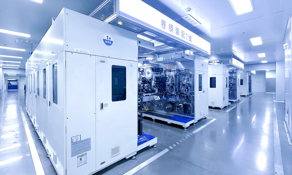
A production winder must coordinate electrode feeding, separator alignment, edge positioning and tension feedback. Process parameters should be linked to the selected cell format, foil thickness, coating width and tab geometry. TOB NEW ENERGY’s 21700 tabless cylindrical battery production line integrates electrode processing, winding, assembly, electrolyte filling, formation and grading around a defined cell design, allowing the interfaces between stations to be engineered as a complete line rather than as isolated machines.
Current-Collector Edge Forming and Flattening
After winding, the exposed foil edges must be formed into a stable end face. This operation is often described as flattening or collector-edge forming. It is not simply a compression step. Excessive force can fold foil fragments into the jelly roll, create particles or close channels needed for electrolyte penetration. Insufficient or uneven force can leave height variation that prevents consistent contact with the collector plate.
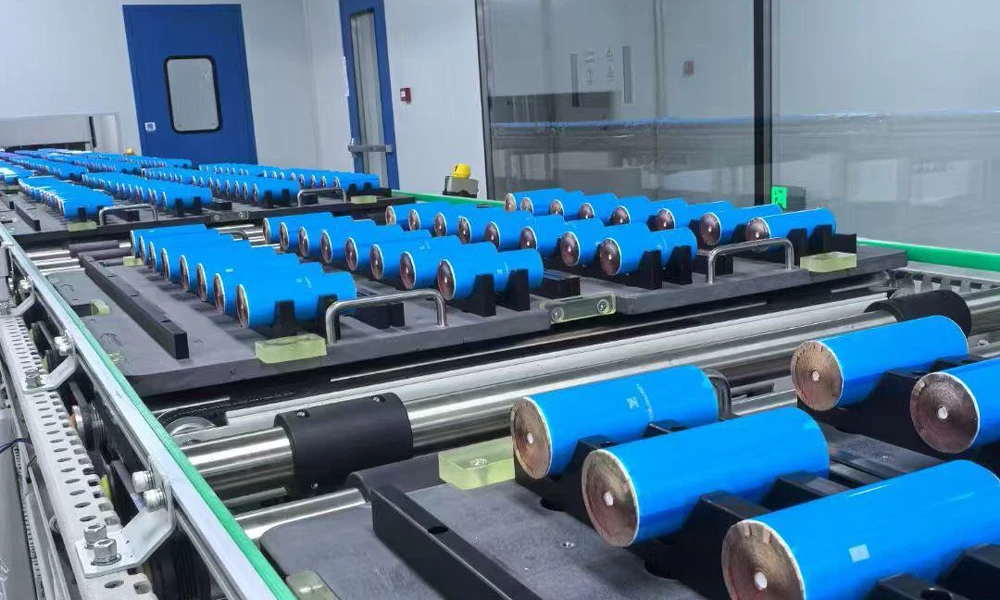
The process therefore needs controlled displacement, force feedback, concentric positioning and recipe management. The target is a repeatable geometry with enough mechanical integrity for handling and enough open structure for downstream wetting. The large cylindrical tabless battery jelly-roll flattening machine is designed for precision forming of the exposed current collectors before welding. In process development, engineers should correlate forming force and displacement with end-face height, particle generation, electrical resistance and electrolyte absorption rather than qualifying the station by appearance alone.
Collector-Plate Laser Welding
The formed end face must then be joined to the positive and negative collector structures. Laser welding is commonly used because it can deliver localized energy at high speed and can be programmed for rings, spirals, segments or other patterns. Yet a larger potential contact area does not automatically produce a lower-resistance joint. Gaps, contamination, oxide layers or inconsistent foil density can cause incomplete fusion, spatter, burn-through or unstable resistance.
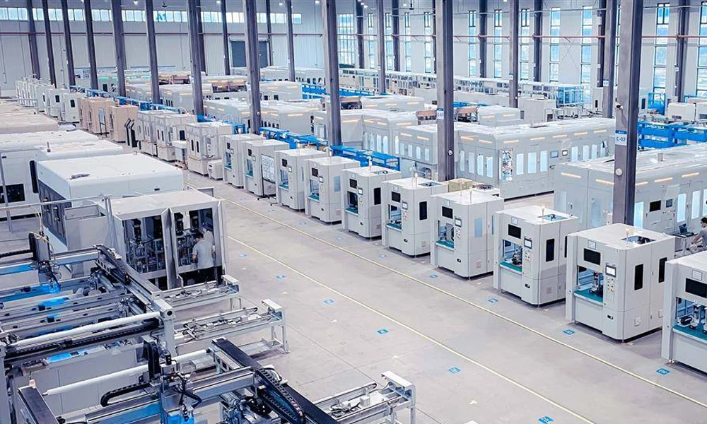
Welding development should define laser power, pulse or continuous-wave mode, focal position, travel speed, shielding, path overlap and acceptable penetration. Vision-based positioning and weld monitoring improve repeatability, but destructive cross-sections and electrical measurements remain necessary during qualification. TOB’s laser welding machine for cylindrical tabless battery current collectors is engineered for precision joining of the anode and cathode current collectors in tabless cylindrical cells.
Electrolyte Filling Is Still a Critical Constraint
One attraction of a tabless end face is its large electrical contact area, but that same geometry can complicate electrolyte access. If collector edges are flattened too densely or the collector plate covers too much of the end surface, liquid may take longer to reach the inner layers of the jelly roll. Poor wetting can increase impedance, reduce usable capacity and create non-uniform ageing even when the weld itself is excellent.
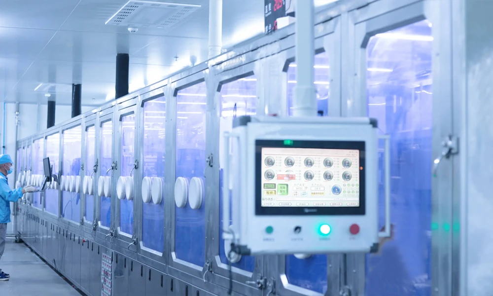
Electrolyte filling must therefore be developed together with edge forming and collector design. The engineering team should evaluate vacuum level, dosing strategy, fill temperature, soak time and any multi-stage filling sequence. Cell mass tracking before and after filling provides a basic check, but it cannot prove uniform wetting. Impedance evolution, X-ray or CT analysis, teardown inspection and electrochemical formation data can reveal dry zones or delayed infiltration.
This is a key systems lesson: optimizing the lowest electrical resistance at the end face may conflict with the need for rapid, uniform electrolyte penetration. The best process window balances both. Line trials should vary forming density, collector-plate opening ratio and filling recipe as coupled factors rather than optimizing each station independently.
Quality Control for Stable Mass Production
Tabless cylindrical cells require quality checks that connect geometry to electrical performance. Before welding, vision systems can inspect electrode overhang, jelly-roll centering and the formed end-face profile. Height maps or displacement measurements help identify uneven regions that could create local welding gaps. Particle control should be monitored because thin metal fragments can become internal short-circuit risks.
During welding, useful process signals include reflected light, plasma emission, temperature response and laser power stability. These signals can flag abnormal events, but they need to be trained against physical weld sections and resistance results. A monitoring waveform alone is not proof of joint quality. After welding, manufacturers can combine pull or peel tests, cross-sectional microscopy, X-ray inspection and low-resistance measurements to build a defensible acceptance window.
End-of-line testing should include open-circuit voltage, AC impedance, DC internal resistance, leakage, capacity grading and high-rate pulse behavior. Thermal imaging during representative discharge is especially valuable because one purpose of the tabless architecture is to improve current and temperature uniformity. Statistical process control should trace anomalies back to winding, flattening and welding recipes, enabling the production line to correct root causes instead of sorting defects only after formation.
How to Evaluate a Tabless Cylindrical Cell Production Line
A line should be evaluated as an integrated manufacturing system, not as a checklist of machines. First, define the cell specification: format, chemistry, capacity, electrode dimensions, collector-edge pattern, terminal design and target current. Then define critical-to-quality values for every interface, including electrode alignment, wound-cell diameter, end-face height variation, welding resistance, electrolyte uptake and final DC resistance.
Second, run design-of-experiment trials across the linked stations. Winding tension can influence edge height; edge-forming pressure can influence both welding and wetting; welding energy can affect separator safety and terminal resistance. The process window must remain capable under realistic material and environmental variation, not only during a single demonstration batch.
Third, require traceability. Each cell should be associated with material lots, recipe versions, station measurements and test results. This is essential when scaling from laboratory samples to pilot production and then to commercial throughput. Finally, assess changeover and maintenance. A line built for one cylindrical format may need different tooling, vision parameters, welding paths and filling recipes for another. Modular fixtures and validated recipes reduce the risk of uncontrolled changes.
TOB NEW ENERGY’s Engineering Perspective
Tabless cylindrical batteries can deliver meaningful advantages in power, thermal behavior and fast-charge potential, but the architecture raises the manufacturing bar. The decisive capability is not a single patented geometry or an isolated machine. It is the ability to maintain alignment, form a controlled conductive end face, create low-resistance welds, preserve electrolyte pathways and verify each result with traceable data.
TOB NEW ENERGY supports customers from process development and pilot validation through integrated cylindrical-cell production. Equipment configuration is tailored to the target cell size, chemistry, collector design, output and quality plan. For projects involving 18650, 21700, 4680 or other tabless formats, early co-development of the cell design and equipment recipes can shorten commissioning and expose manufacturability risks before high-volume tooling is finalized.
As high-power markets expand across tools, robotics, aviation, mobility and backup power, tabless technology is likely to become an increasingly important option. Its success, however, will be measured by stable yield and reproducible cell performance—not by the tabless label alone.
Frequently Asked Questions
Is a tabless battery completely free of tabs?
No. The term generally describes a distributed current-collection edge that replaces a small number of discrete welded tabs. The edge is still joined to a collector plate, cap or terminal structure to conduct current out of the jelly roll.
Can a tabless design automatically guarantee faster charging?
No. Lower resistance and improved thermal uniformity can support higher charging power, but safe fast charging also depends on cathode and anode chemistry, negative-to-positive capacity ratio, electrolyte transport, temperature control and the charging protocol. Lithium-plating risk must be validated at cell level.
What is the most difficult process in tabless cylindrical cell production?
There is no single universal bottleneck. Precision winding, collector-edge flattening, laser welding and electrolyte wetting are closely coupled. In many projects, yield is determined by the interaction between end-face geometry and weld consistency rather than by either station alone.
Which cell formats can use tabless architecture?
The principle can be applied to multiple cylindrical formats, including 18650, 21700, 4680 and custom large cylindrical cells. Equipment and tooling must be configured for the specific electrode width, jelly-roll diameter, edge design, terminal structure and production target.
What data should be collected during pilot-line validation?
Recommended data include winding tension and alignment, jelly-roll dimensions, end-face height distribution, forming force and displacement, weld-monitoring signals, weld resistance, electrolyte uptake, formation curves, DC internal resistance, capacity, rate capability and thermal images under representative loads.
Source note: This article is an independently written technical interpretation based in part on the supplied battery-industry overview published on WeChat on October 21, 2026. Manufacturer performance figures in that source use different test conditions; this article therefore avoids direct product ranking and treats those figures as contextual rather than directly comparable evidence.
Contact TOB NEW ENERGY
Contact: Amy Wang
Email: tob.amy@tobmachine.com
Mobile: +86-18120715609
Official Website: https://www.tobmachine.com/
Address: NO.1633, Jicheng Road, Tong'an torch Industry Phase II, Tong'an District, Xiamen City, Fujian Province, China
 우리를 구독