Chinese
 English
 français
 Deutsch
 italiano
 español
 português
 Nederlands
 日本語




- 홈
- >
카테고리
핫 제품
Patent CN215612935U - Liftable Heating & Dehumidifying Unit
Oct 26,2026A mobile, electrically liftable unit that heats the coating machine exactly where it works - and condenses moisture out of the air so the heater stays dry and rust-free.
Full specification and drawings: CN215612935U on Google Patents
A coating machine's working temperature is not a comfort issue - the specification says temperature has a great influence on the working efficiency of the coating machine, and that poor heating can seriously waste lithium battery production materials. Yet heating a web coating line is not the same as heating a room: the heat must reach the machine at the right height, at the right moment, without being dragged down by the humid air that a coating and drying process constantly releases.
CN215612935U, filed on 1 September 2021, answers with a self-contained unit that can be wheeled to any point of the line. Its electric cylinder lowers the heating frame to the working height, an electric heating tube heats the coating machine while it runs, and a cross-flow fan draws the humid air through a moisture-condensing plate - so the heating element is never soaked, never rusted, and never idle.
Patent Information
| Publication number | CN215612935U |
| Title (original) | 一种用于锂电池涂布机的可升降加热装置 (Liftable Heating & Dehumidifying Unit for Coaters) |
| Inventors | Huang Zhengyao (Dany Huang); Chen Lucai (Tobey Chen) |
| Current assignee | XIAMEN TOB NEW ENERGY TECHNOLOGY Co., Ltd. - the registered entity of TOB NEW ENERGY |
| Filing date | 1 September 2021 |
| Grant date | 25 January 2022 |
| Document type | Utility model (granted, kind code U) |
| Legal status | Active |
| Anticipated expiration | 1 September 2031 |
| Drawings | 6 figures |
The Production Problem This Patent Solves
Coating machines apply a functional layer - adhesive, coating, ink or the like - to a coiled substrate, dry it and rewind it. Two environmental factors fight that process. The first is temperature: when the machine runs too cool, coating efficiency drops and material is wasted. The second is moisture: humid air around the machine attacks the very heating elements that should be doing the drying, leading to rust and premature failure. The patent names the defect it corrects in one line: the coating machine's heating effect was poor.
How the Mechanism Works
The unit stacks four sub-assemblies on one chassis: a telescopic device (1), a heating device (2), a fan device (3) and eight caster wheel sets (4), all supervised by a controller (5).
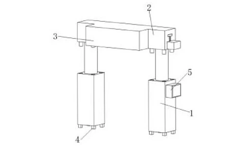
Mobile, height-adjustable platform
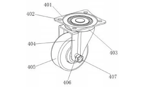
The telescopic device (1) is an electric cylinder (101) with a telescopic rod (102) at its top, standing on eight caster wheel sets (4) - so the unit is wheeled to the coating machine and the rod then lowers the heating frame to the required height under controller command. The caster wheel set is a connecting frame (401) bolted through threaded holes (402), a rotating connecting block (403), a wheel frame (404) and a caster wheel (405) locked by a fixed shaft (406) and nut (407), with a rolling bearing allowing the wheel to swivel.
Shock absorption for the lifting frame
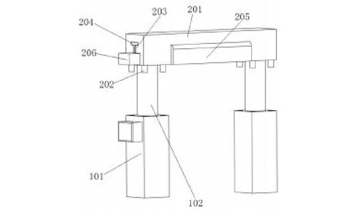
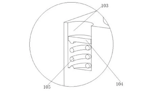
At the four corners of the electric cylinder, damping ports (103) hold buffer plates (104) that ride on damping springs (105); each plate is a circular panel with a felt pad on its upper face. Matching damping blocks (202) on the underside of the heating frame - cylinders of the same diameter as the buffer plates - land on these pads, so the raised heater is cushioned rather than jarred.
Heating device
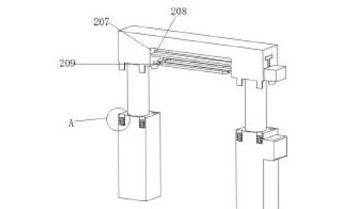
The heating device (2) is a heating frame (201) with an electric heating tube (209) at the middle of its lower end, wired to the controller. When the frame is lowered to the working position, the tube heats the coating machine during operation - the mechanism the specification credits for effectively raising coating machine working efficiency.
Moisture-condensing air circuit
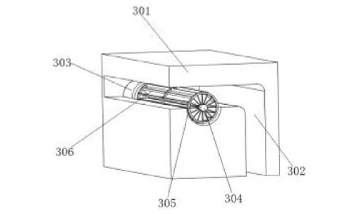
Humid air is drawn through a suction port (205) at the right of the heating frame into air passages (207) that run through the frame on both sides of the moisture treatment trough (203). A moisture-condensing plate (204) stands in the middle of the trough; the trough and the plate are both T-shaped and fit with a clearance. The fan device (3) - a fan box (301) with a 7-shaped fan duct (302), its motor (303) turning a shaft (304) that carries arc-shaped fan blades (306) on blade frames (305), the shaft end supported in the fan box by a bearing - pulls hot, humid air over the cold condensing plate. Water droplets form on the plate surface; dry air leaves from the other end of the fan duct and cools the material after heating.
Condensate drainage
Droplets on the condensing plate fall naturally to a water collecting trough (208) below it - an inclined arcuate plate - and drain through its outer end into a water tank (206). The collected moisture is carried away from the machine instead of returning to the air, which is what keeps the electric heating tube dry, rust-free and long-lived.
Claimed Benefits
| Benefit | Mechanism responsible |
|---|---|
| On-demand heating while the coater runs | Electric heating tube on the lowered heating frame |
| Higher coating machine efficiency | Heat delivered at the machine position at the required height |
| Heater protected from moisture and rust | Cross-flow fan drawing air over the moisture-condensing plate |
| Condensate removed from the work area | Inclined collecting trough draining to the water tank |
| Easy repositioning and height setting | Eight caster wheel sets and an electric-cylinder lift |
| Vibration-free raising of the heater | Damping springs, buffer plates and damping blocks |
How It Compares with Fixed Heating Around a Coater
Two environmental factors fight the coating process: when the machine runs too cool, coating efficiency drops and material is wasted, and humid air attacks the equipment and causes rust. A fixed heater can solve neither at the right position.
| Dimension | Conventional approach | This patent design |
|---|---|---|
| Positioning | Fixed heater at a set location and height | Mobile unit on eight caster sets with an electric-cylinder lift |
| Moisture | Humid air rusts the heater and machine | Cross-flow fan draws air over a moisture-condensing plate, condensate drains to a tank |
| Raising | Manual or vibration-prone lift | Damping springs, buffer plates and damping blocks absorb shock while lifting |
Where This Technology Is Used Today
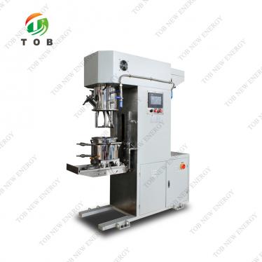
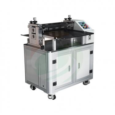
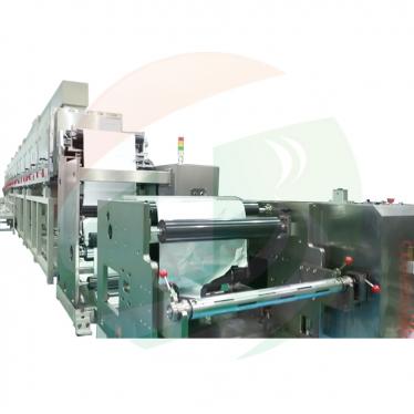
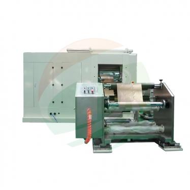
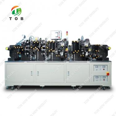
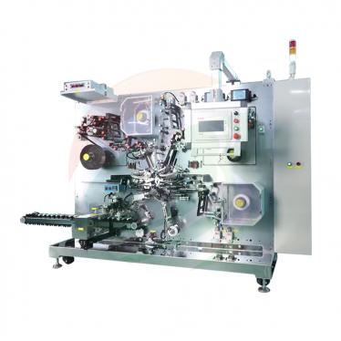
This patent covers the mobile heating and dehumidifying support behind TOB's coating machines. The combination it protects - electric lifting, on-site radiant heat and condensing moisture removal - is how our coating lines hold a stable thermal environment around the coating head and drying section.
- Roll-to-roll battery electrode coating machine - continuous coating equipment for lithium-ion electrode preparation
- Battery coating machines - coaters and film applicators for laboratory and production use
Related equipment enquiries: request a quote
Frequently Asked Questions
What does patent CN215612935U cover?
It covers a liftable heating and dehumidifying unit for lithium battery coating machines: a telescopic device with an electric cylinder and rod standing on eight caster wheel sets, a heating frame carrying an electric heating tube, and a fan device that draws humid air over a moisture-condensing plate, with the condensate drained into a water tank.
Why does a coating machine need a separate heating unit?
The specification states that temperature has a great influence on the working efficiency of a coating machine, and that poor heating can seriously waste lithium battery production materials. This unit delivers heat to the coating machine at the required position and height while the machine is working.
How does the unit remove moisture from the air?
A cross-flow fan draws humid air through the suction port and air passages into the moisture treatment trough, where it meets the cold T-shaped condensing plate. Water droplets condense on the plate surface while dry air leaves from the other end of the fan duct, and the droplets fall into a collecting trough that drains to a water tank.
Why remove moisture at the heating position at all?
Moisture in the working air would otherwise reach the electric heating tube, causing rust and premature failure. Condensing the moisture out of the air keeps the heating element dry, extends its life and protects the material being processed.
How is the heating frame raised and lowered?
The controller starts the electric cylinder, whose telescopic rod moves the heating frame down to the required height. Damping ports with sprung buffer plates and felt pads, matched by damping blocks under the heating frame, cushion the movement, and the unit is repositioned on its eight caster wheel sets.
Is patent CN215612935U still in force?
Yes. It is Active, filed on 1 September 2021 and granted on 25 January 2022, with anticipated expiration on 1 September 2031.
Full specification and drawings: CN215612935U on Google Patents
 우리를 구독