Chinese
 English
 français
 Deutsch
 italiano
 español
 português
 Nederlands
 日本語
日本語




- 홈
- >
카테고리
핫 제품
특허 CN215451487U - 퀵 체인지 다이 방식의 실험실용 실러
Sep 22,2026R&D 배터리 샘플을 위한 소형의 글로브 박스 친화적 실링 프레스: 상부 다이는 나사산 장부와 핀을 통해 교체되며, 하부 다이 홀더는 청소를 위해 슬라이드 방식으로 분리됩니다.
전체 사양 및 도면: Google Patents의 CN215451487U
연구용 샘플을 만드는 것은 생산용 셀을 만드는 것과는 다른 작업입니다. 실험실용 배터리 실링기는 소량의 실험 재료를 다루며(종종 글로브 박스 내부에서 사용), 샘플이 바뀔 때마다 적응해야 합니다. 이 사양은 기존 기술의 한계를 솔직하게 설명합니다. 실험실용 실링기의 실링 장치는 종류가 다양했으며, 다른 종류의 배터리를 실링하려면 일치하는 다이 실링 홈을 분리하고 재설치해야 했으며, 이는 불편하고 번거로운 작업이었습니다.
CN215451487U는 이러한 번거로움을 제거합니다. 상부 실링 다이는 핀으로 고정된 나사산 장부로 유지되므로 즉시 나사를 풀고 교체할 수 있습니다. 하부 다이 홀더는 슬라이딩 플레이트 위에서 작동하며 설치 및 청소를 위해 레일을 따라 당겨낼 수 있습니다. 또한, 프레스가 높은 힘으로 작동할 때 슬라이딩 플레이트를 보호하는 지지 장치가 포함되어 있습니다.
특허 정보
| 공개 번호 | CN215451487U |
| 출원 번호 | CN202122023872.8U |
| 제목 (원문) | 一种可自由更换封口装置的电池封口机 (퀵 체인지 다이가 포함된 실험실용 배터리 실링기) |
| 발명자 | Huang Zhengyao (Dany Huang); Chen Lucai (Tobey Chen) |
| 현재 권리자 | XIAMEN TOB NEW ENERGY TECHNOLOGY Co., Ltd. - TOB NEW ENERGY의 등록 법인 |
| 출원일 | 2021년 8월 26일 |
| 등록일 | 2022년 1월 7일 |
| 문서 유형 | 실용신안 (종류 코드 U) |
| 법적 상태 | 유효 |
| 만료 예정일 | 2031년 8월 26일 |
| 도면 | 5개 도면 |
| 공식 기록 | Google Patents의 CN215451487U |
이 특허가 해결하는 생산 문제
모든 샘플 유형에는 고유한 다이가 필요합니다.실험실 실러는 배터리 소재의 연구 개발 샘플을 만드는 데 사용됩니다. 배터리 유형마다 다른 다이 실링 홈이 필요하므로 다이를 빠르게 교체할 수 없는 기계는 실링 작업보다 재설정 작업에 더 많은 시간을 소비하게 됩니다.
교체 및 청소의 번거로움.다이 홈은 수동으로 분리 및 재설치해야 하며, 기계에서 꺼낼 수 없는 실링 다이는 작업 사이에 제대로 청소하기가 어렵습니다.
실험실 프레스는 실제 가압력을 견뎌야 합니다.샘플 실링에는 여전히 힘이 필요하며, 명세서에서는 과도한 압력이 슬라이딩 플레이트를 손상시키거나 균열을 일으킬 수 있다고 경고합니다. 이 특허는 빠른 다이 교체, 슬라이드 방식의 하부 다이 스테이션, 하중을 지탱하는 지지 장치라는 세 가지 문제를 모두 해결합니다.
메커니즘 작동 원리
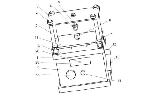
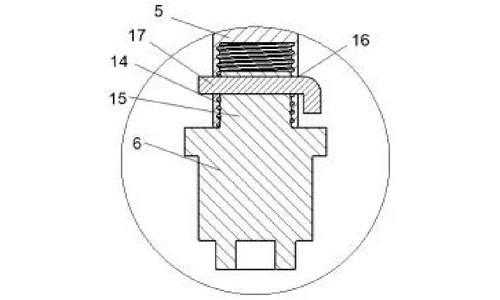
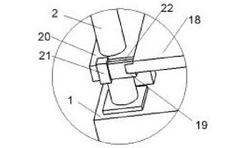
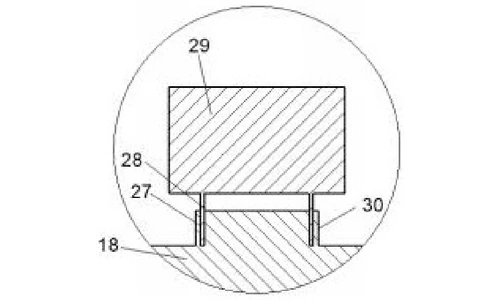
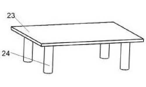
이 기계는 기계 베이스 위에 소형 프레스 형태로 제작되었으며, 램 앞쪽 슬라이드에 다이 스테이션이 있고 아래 본체에 압력 제어 장치가 있습니다. 그림 1은 전체 구조를 보여주고, 그림 2는 프레스 영역의 A 부분을 확대한 것이며, 그림 3은 지지 장치를 보여줍니다. 그림 4와 5는 상부 및 하부 다이가 장착되는 방식을 보여줍니다.
프레스 프레임 및 램
기계 베이스 위에 지지 컬럼이 고정되어 있고, 스탬핑 작업대가 볼트를 통해 컬럼 상단에 이동 가능하게 연결되어 있습니다. 스탬핑 컬럼이 작업대 하단에 매달려 상부 실링 다이를 지지합니다. 베이스 아래에는 기계 본체가 있으며, 전면에는 압력계와 압력 조절 밸브가 있고, 우측에는 프레스 스위치 시트와 프레스 레버가 있습니다. 실링 다이를 보관할 수 있는 손잡이가 달린 서랍이 본체에 장착되어 있습니다.
퀵 체인지 상부 실링 다이
스탬핑 컬럼의 하단에는 내부 나사산이 있는 원통형 구멍이 있습니다. 상부 실링 다이에는 원통형 돌출부 상단에 외부 나사산이 있습니다. 다이는 컬럼에 나사로 고정되며, 두 부품 모두 정렬된 원형 구멍이 있어 그 사이로 원통형 핀이 삽입됩니다. 이 핀은 프레스 작업 중 나사 조인트가 풀리거나 돌아가는 것을 방지합니다. 다이를 교체하려면 작업자가 핀을 빼고 다이를 돌려 빼면 됩니다. 사양서에 따르면 이것이 상부 실링 다이를 교체하기 쉽고 분해하기 쉽게 만드는 요소입니다.
슬라이드식 하부 다이 스테이션
기계 베이스 위에는 지지 장치가 있고, 그 위로는 슬라이딩 플레이트가 레일 위에 장착되어 움직입니다. 레일은 지지 컬럼을 통과하여 가압 하중의 일부를 분담하는 지지 프레임에 의해 지지됩니다. 하부 다이 고정 장치는 원형 돌출부와 링 홈으로 구성되어 있으며, 하부 실링 다이 밑면의 중공 실린더를 수용하고 슬라이딩 플레이트에 장착됩니다. 지지 프레임의 슬라이드 블록 볼트는 작은 홈을 따라 이동하며 슬라이딩 플레이트의 위치를 제한하고 고정합니다. 전체 하부 다이 홀더가 슬라이드 위에 있기 때문에 다이 설치 및 청소를 위해 플레이트를 따라 밖으로 당길 수 있습니다.
슬라이드 하부의 지지 장치
지지 장치는 지지 플레이트와 4개의 지지 컬럼으로 구성되며, 하단은 기계 베이스에 매립되어 있습니다. 지지 컬럼을 통과하는 지지 프레임과 함께 가압력의 일부를 흡수합니다. 사양서에 따르면 이러한 구조는 과도한 압력 하에서 슬라이드 플레이트가 손상되거나 균열되는 것을 방지합니다.
공개된 작동 순서
실험자는 압력계를 확인하고 실험에서 규정한 압력으로 조절 밸브를 조정합니다. 하부 실링 다이의 중공 실린더를 슬라이딩 플레이트의 원형 돌출부 링 홈에 안착시키고, 상부 실링 다이를 스탬핑 컬럼에 나사로 고정하여 원통형 핀으로 잠급니다. 실링할 배터리 재료를 하부 다이 위에 놓고 프레스 레버를 아래로 누르면 실링이 완료됩니다.
주장된 이점
| 이점 | 담당 메커니즘 |
|---|---|
| 교체 가능하고 분해가 쉬운 상부 다이 | 나사산 원통형 테논 및 원통형 핀 잠금 장치 |
| 편리한 다이 설치 및 세척 | 슬라이딩 플레이트와 레일을 통해 하부 다이 고정 장치를 인출 가능 |
| 과도한 압력으로부터 보호되는 슬라이드 플레이트 | 지지 장치(4개의 내장 지지 기둥이 있는 지지 플레이트) 및 하중 분산 지지 프레임 |
| 제어 가능하고 반복 가능한 가압력 | 본체에 장착된 압력계 및 압력 조절 밸브 |
고정 다이 실험실 실러와의 비교
배터리 샘플 유형마다 서로 다른 실링 다이가 필요합니다. 다이를 빠르게 교체할 수 없는 실러는 실링 작업 대신 재공구화(re-tooling)에 대부분의 시간을 소비하게 되는데, 이는 본 특허가 해결하는 바로 그 문제입니다.
| 치수 | 기존 방식 | 본 특허 설계 |
|---|---|---|
| 상부 다이 교체 | 샘플 유형 간 느린 재공구화 | 나사산 테논과 핀을 통한 빠른 상부 다이 교체 |
| 하부 다이 접근 | 세척을 위해 접근하기 어려움 | 슬라이딩 플레이트와 레일을 통해 하부 다이 스테이션을 인출 |
| 압력 제어 | 일관되지 않은 수동 설정 압력 | 슬라이드 아래 하중 분산 지지대가 있는 압력계 및 조절 밸브 |
이 기술이 현재 사용되는 곳
본 특허는 TOB의 실험실용 배터리 실링 장비의 퀵 체인지 다이 아키텍처를 다룹니다. 이는 연구용 코인 셀 및 샘플 셀을 압착하고 실링하는 데 사용되는 동일한 워크스테이션 제품군으로, 몇 초 만에 다이를 교체할 수 있습니다.
관련 장비 문의: 견적 요청
자주 묻는 질문
특허 CN215451487U는 무엇을 다루나요?
이 특허는 배터리 재료의 R&D 샘플을 제작하는 데 사용되는 실험실용 배터리 실링 기계를 다루며, 글러브 박스 작업에 적합한 콤팩트한 크기와 특수 유압 프레스 구조를 갖추고 있습니다. 주요 특징으로는 빠르게 교체 가능한 상부 실링 다이, 다이 설치 및 세척을 위해 인출 가능한 슬라이딩 플레이트에 장착된 하부 다이 고정 장치, 슬라이드 플레이트의 압력 손상을 방지하는 지지 장치가 있습니다.
실험실용 실러에서 퀵 체인지 다이가 중요한 이유는 무엇인가요?
배터리 유형마다 서로 다른 다이 실링 홈이 필요합니다. 이전의 실험실용 실러에서는 배터리 유형을 바꿀 때마다 일치하는 홈을 분리하고 다시 설치해야 했는데, 이는 사양서에서 불편하고 번거로운 작업으로 설명됩니다. 퀵 체인지 툴링을 사용하면 작업자가 다이를 교체하고 즉시 샘플 실링 작업을 재개할 수 있습니다.
상부 실링 다이는 어떻게 부착되어 빠르게 교체할 수 있나요?
스탬핑 기둥의 하단에는 내부 나사산이 있는 원통형 구멍이 있고, 상부 실링 다이의 상단에는 외부 나사산이 있는 원통형 돌기가 있습니다. 다이를 기둥에 나사로 조인 후, 두 부품의 정렬된 원형 구멍에 원통형 핀을 삽입하여 결합부를 잠급니다. 핀을 풀고 다이를 돌려 빼면 교체가 완료됩니다.
하부 실링 다이는 어떻게 세척하거나 교체하나요?
하부 다이 고정 장치는 지지 장치 위의 레일을 따라 움직이는 슬라이딩 플레이트에 장착되어 있습니다. 홀더 전체를 슬라이딩 플레이트를 따라 밖으로 당길 수 있어 프레스를 분해하지 않고도 편리하게 다이를 설치하고 세척할 수 있습니다.
특허 CN215451487U의 소유자는 누구인가요?
TOB NEW ENERGY가 이 등록된 실용신안을 보유하고 있습니다. 이 특허는 등록된 중국 법인 명의로 출원되었으며, Huang Zhengyao(Dany Huang)와 Chen Lucai(Tobey Chen)가 공동 발명했습니다.
특허 CN215451487U는 여전히 유효합니까?
네. 활성 상태이며, 2021년 8월 26일에 출원되었고 2031년 8월 26일에 만료될 예정입니다.
전체 명세서 및 도면:Google Patents의 CN215451487U
 우리를 구독